31. A Mechanical Cookbook
31.1 Connectors
31.1.1 Bearings
• The interface between moving parts that should minimize friction and wear.
31.1.1.1 - Plain Bearings
• Generally used in low speed machines.
• The main bearing action comes from the lubricant.
31.1.1.1.1 - Solid Bearings
• This looks like a section of tube that is placed in a hole, and the shaft rotates inside.
• Typical materials are,
bronze
sintered bronze (with graphite)
cast iron
• Made for slowly rotating equipment
• lubrication is required, and problems will arise when not properly maintained.
• Available in standard sizes.
31.1.1.1.2 - Split Bearings
• Used on large machines at low speeds.
• The two halves of the bearings are adjusted in position using shims.
• Typical materials include,
bronze
bronze with babbitt
babbitt lined metal
• Oil grooves are used for lubrication.
31.1.1.1.3 - Thrust Bearings
• Opposes axial thrusts of rotating shafts.
• Uses shoes of a variety of shapes,
flat
kidney shaped
• An oil wedge approach is used to support the bearing.
31.1.1.2 - Rolling Bearings
• Advantages,
low friction at all times
compact
high accuracy
low wear
come in standard sizes
31.1.1.2.1 - Ball Bearings
• Low friction, high speeds, low loads.
• ball bearings are packed between two rotating rings.
• The grooves that contain the ball bearings is given different shapes for different loading conditions.
31.1.1.2.2 - Roller Bearings
• For heavy loads at medium or high speeds.
• The various roller bearings are designed for loads (radial and axial) and packing space.
31.1.1.2.3 - Thrust Bearings
• A set of rollers or balls are held between two washers.
• Designed mainly for lower speed axial loads and occasionally light radial loads.
31.1.2 Threads
• One of the classic forms of mechanical connector. Also used to magnify motion and force, and to convert rotation to linear motion.
• The basic terminology is,
• Right hand threads are turned clockwise to tighten, left hand threads are turned the other way.
• Threads Per Inch (TPI) are the number of turns of the thread per inch of length.
• There are a number of standard threads, as outlined in the following subsections.
31.1.2.1 - Metric
31.1.2.2 - American National Standard
31.1.2.3 - British Standard Whitworth (BSW)
31.1.2.4 - The Unified Thread
31.1.2.5 - American National ACME Thread
31.1.2.6 - Brown and Sharpe Worm Thread
31.1.2.7 - Square Thread
31.1.3 Tapers
31.2 Motion and Force Transmissions
31.2.1 Gears
• Gears are generally round or linear sets of teeth for transmitting forces or motions.
• Different combinations of gears will allow conversions of forces, motions and directions.
• Different types of gears are,
spur
internal
helical
herringbone
bevel
hypoid
worm
rack and pinion
31.2.1.1 - Spur Gears
• transmit power between parallel shafts
• have straight teeth parallel to axis of rotation
• used for slow/moderate speeds
• when two of these gears are meshed, the larger is the gear, the smaller is the pinion
31.2.1.2 - Internal Gears
• transmission between parallel shafts
• require less space
• better meshing/more contact between gears.
31.2.1.3 - Helical Gears
• Gears with teeth on an angle.
• can convert rotary motion to rotary motion on a non-parallel shaft.
• a tooth does not suddenly engage/disengage fully, so noise and vibration are reduced.
• also, more than one tooth is typically in contact, so the strength is increased.
• these gears often generate longitudinal forces that require thrust bearings.
31.2.1.4 - Herringbone Gears
• Looks like a helical gear, but it looks as if a second helical gear with a reverse helix has been attached.
• Similar to helical gears, except that thrust bearings are not required.
31.2.1.5 - Bevel Gears
• Transmit rotations to another axis perpendicular to the first.
• These gears look like spur gears, but with a taper.
• When the two gears are the same size they are miter gears.
• for non-90° intersections, the gears are called angular bevel gears.
• the rotational axes of these gears intersect.
31.2.1.6 - Hypoid Gears
• Like bevel gears, but with helical teeth
• the gears are often offset also (the axes of rotation do not intersect)
• these gears are commonly used in the auto industry.
31.2.1.7 - Worm Gears
• The worm is a helical gear with one or more threads.
• The worm gear is typically a straight tooth gear that is turned by the worm.
• This combination is used to convert rotation to a perpendicular rotation, and reduce the speed.
31.2.1.8 - Rack and Pinion
• A rotating spur gear drives a linear rack of teeth.
• this combination converts a rotation to a linear motion.
31.3 Power Transmission
31.3.1 Hydraulics
• Incompressible fluids are used to transmit volume and pressure changes throughout a system.
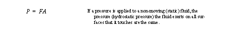
• Pascal’s law basically describes these systems,
• Hydrostatic force/motion multiplier,
• The Hydrodynamic Effect: when fluid is moving quickly, it has high levels of kinetic energy. If the fluid impacts a surface, it transmits a high quantity of energy in a short period of time.
• Hydraulic Circuits typically contain,
1. Hydraulic Fluid
2. An Oil Reservoir
3. A Pump to Move Oil, and Apply Pressure
4. Pressure Lines
5. Control Valves: to regulate fluid flow
6. Piston and Cylinder: to actuate external mechanisms
• Oil Reservoirs
• Pump types used include,
Reciprocating pumps: have intermittent pressures with a single piston
• Valves